


Maintenance Index
Complimentary PDF Library
Here you will find PDF Docs of the Workshop manual to compliment the sections of this page. You will also find important safety and correct jack and axle stand positions. Always ensure your safety when working beneath a veichle.
If there is more information you require on a subject contained on this page, please feel free to contact me through the 'Links' page.
Front Brake Pads

Tools Required
Wheel removal sockets (19mm or 21mm), breaker bar, 14mm socket, 7mm allen key, wide screwdriver, C-Clamp & thin piece of wood, torque wrench, copper high-temp antiseize grease or similar. Front brake pads. Hydraulic jack and U-top jack stands.
Brake Pad Min Thickness
The replacement thickness of front brake pads is 1mm, replace pads across an axle. Caliper's outer face contains a square cut pad inspection window.
Front Brake Pads
Stock brake pads provide effective stopping distances, however there are alternatives offering less dust (Axxiss Metal Master) or better performance (Carbon or Kevlar brake pads). Racing pads should not be used on the street because initial braking or emergency braking performance will be impeded.
Jack up car & remove wheel(s)
- Ensure the handbrake is firmly applied, the car is level and in Gear/Park. Jack up the front of car using a proper hydraulic jack & support on jack stands at the proper Jacking & Support Points.
- Just before the wheel(s) clear the ground, slightly release the 5 wheel nuts otherwise removal will prove difficult with the wheel in the air.
- With the car safely supported on jack stands, proceed to remove the wheel nuts & wheel. Alloy wheels will fall onto the spokes if left to roll.
Removing pads from brake callipers
- Locate the lower caliper guide bolt, its end is capped in a small black plastic cylinder. The caliper hinges about the upper guide bolt. A 14mm socket or 7mm allen key is required to them remove the bolt.
- The Caliper guide bolt is chromed and should be lubricated with a high temp grease (copper antiseize). If the chrome is heavily peeled and brakes are wearing unevenly the guide bolt should be replaced. Unless the caliper can slide freely braking will be on one side of the brake rotor only which will reduce breaking performance considerably.
- Swing the calliper up & out of the way. You will see two wide V-springs (wire based) and guide plates (convoluted metal clip). The two act as kick-back springs against the brake pads.
- Brake pads themselves snap into the Guide Plates, first remove the V-springs and the pads should unclip with light levering. Remove the outer & inner shims from each pad, noting their order & orientation onto the pegs on the rear of the brake pads. Re-use the shims if there are none with new brake pads, or obtain new from the dealer.
- Place a thin coating of copper antiseize grease between each of the shims and the brake pad, taking care not to get any on the rotor or brake pad surface. This avoids brake squeal and rattle.
- Before fitting the new brake pads the FRONT calliper piston must be pushed back into the caliper sufficiently. (On the REAR the pistons must never be pushed back, they are wound back by a allen-bolt itself hidden under a hex-bolt at the rear of the caliper in line with the brake piston itself).
- Taking the C-Clamp and a piece of wood, or a proper brake-piston-retractor, push the piston back into the caliper. The piston must be pushed back parallel with it's bore or damage to both will result. The seal on the piston must not be damaged either. Snap the brake pads into the caliper, and replace the V-springs. Ensure the pads are seated fully and the shims haven't slipped (hence the anti-seize grease to assist).
- Swing the caliper & brake-pad assembly back onto the rotor, ensuring the pads will pass the rotor edge. Then refit & tighten the caliper guide bolt to 44-49Nm, 33-36lb/ft.
- On completing the pad change, verify the master cylinder is at the appropriate full mark with fresh DOT3 or DOT4 brake fluid.
Bleeding brakes
- The brakes should now be bled to eliminate any air or moisture which has got into the system, and indeed they should be bled annually anyway.
- See the Brake Bleeding & Brake Fluid Change section for the method.
Finishing Off
- Refit caliper guide bolt cover and wheel, putting a small amount of copper antiseize grease on the hub-wheel interface. Retorque wheel lug-nuts in a 1-3-5-2-4 pattern first to 50lb/ft then 80lb/ft to ensure even tightening & reduce chance of rotor warpage/wheel vibration.
Torque Figures
- Caliper guide bolt torque: 44-49Nm, 33-36lb/ft.
- Wheel torque: 80lb/ft.
Front Brake Discs

Tools Required
Wheel removal sockets (19mm or 21mm), breaker bar, 13 & 17mm socket, rubber hammer, 7mm allen-key, pozidrive/philips screwdriver, torque wrench, copper high-temp antiseize grease or similar. Hydraulic jack and U-top (not V-top) safety jack stands. M8 bolt & matching socket. Piece of steel wire strong enough to hold weight of calliper & bracket. C-Clamp and piece of wood. Some calipers may use a 5/8" bolt.
Brake Rotor/Disc Min Thickness
Replacement thickness of the front brake disc is 22mm (new is 24mm) with runout 0.1mm maximum. Replace rotors across the axle. Thickness is measured by a vernier caliper at several points around the disc and at several distances from the centre of the disc.
Front Brake Rotors
US: Trussville Mazda (www.trussvillemazda.com) do front rotors for ~60$US.
Jack up car & remove wheel(s)
- Ensure the handbrake is firmly applied, the car is level and in Gear/Park. Jack up the front of car using a proper hydraulic jack & support on jack stands at the proper Jacking & Support Points.
- Just before the wheel(s) clear the ground, slightly release the 5 wheel nuts otherwise removal will prove difficult with the wheel in the air.
- With the car safely supported on jack stands, proceed to remove the wheel nuts & wheel. Alloy wheels will fall onto the spokes if left to roll.
Removing calipers from hub
- Follow the 'Front Brake Pad procedure to remove pads and then continue.
- Rotor removal requires the calipers & their bracket be first removed from the hub, achieve by locating the two 19mm bolts retaining them. On US/Canada cars a 7mm allen key is required. The caliper must be supported by a wire to the strut above before the final bolt is removed, it must not be allowed to hang on the brake line even momentarily.
- With the caliper out of the way the rotor is exposed and may be removed by inserting an M8 bolt-thread pre-tapped in the rotor. If the rotors have no such hole, then a rubber hammer is needed on the rear of the rotor to dislodge it.
- If the new rotor is thicker than the old (likely) then the pads will no longer fit back. Thus the pads must be removed (see front brake pad procedure) and the piston pushed back in, then the pads refitted.
Caliper refitting
- Caliper refitting is the reverse of removal, taking care not to damage the piston boot when pushing the pads/caliper back around the brake rotor. Caliper bracket mounting bolts should be torqued to 78-102Nm or 58-74lb/ft.
Bleeding brakes
- See the Brake Bleeding & Brake Fluid Change section for the method.
Finishing Off
- Refit caliper guide bolt cover and wheel, putting a small amount of copper antiseize grease on the hub-wheel interface. Retorque wheel lug-nuts in a 1-3-5-2-4 pattern first to 50lb/ft then 80lb/ft to ensure even tightening & reduce chance of rotor warpage/wheel vibration.
Torque Figures:
- Caliper Bracket mounting bolts torque: 78-102Nm or 58-74lb/ft.
- Wheel Lug Nut torque: 80lb/ft.
Rear Brake Pads
Tools Required
Wheel removal sockets (19mm or 21mm), breaker bar, 13 & 17mm socket, rubber hammer, 7mm allen-key, pozidrive/philips screwdriver, torque wrench, copper high-temp antiseize grease or similar. Hydraulic jack and U-top (not V-top) safety jack stands.
Rear Brake Pad Min Thickness
The replacement thickness of rear brake pads is 1mm, replace pads across the axle. Calipers have a square cut-out inspection window in the middle of their outer face.
Jack up car & remove wheel(s)
- Ensure the handbrake is firmly applied, the car is level and in Gear/Park. Jack up the front of car using a proper hydraulic jack & support on jack stands at the proper Jacking & Support Points.
- Just before the wheel(s) clear the ground, slightly release the 5 wheel nuts otherwise removal will prove difficult with the wheel in the air.
- With the car safely supported on jack stands, proceed to remove the wheel nuts & wheel. Alloy wheels will fall onto the spokes if left to roll.
Removing pads from brake calipers
- Locate the upper caliper guide bolt, the end is dust-cap'd by a small black plastic cylinder. The calipers hinge on the lower bolt when this upper bolt is removed by a 14mm socket or 7mm allen key.
- The Calliper guide bolt is chromed and should be lubricated with a high temp grease (copper antiseize). If the chrome is heavily peeled and your brakes are wearing unevenly (rear calipers not pre 5-Jan-95) then replace the caliper guide bolts. If the caliper can't slide on the bolt effortlessly then braking will be on one rotor side only resulting in reduced braking performance.
- Swing the caliper out of the way, you will see two wide V-springs (wire based) and guide plates (convoluted metal clip). They are designed to maintain pressure against the pads as kick-back springs.
- Brake pads themselves snap into the Guide Plates, first remove the V-springs and the pads should unclip with light levering. From each pad remove the shim and note their orientation on the brake pad pegs. If your new brake pads do not have these shims (available from Dealers) you can re-use the old ones. Place a thin coating of copper antiseize between each of the shims and the brake pad, taking care not to get any on the rotor or brake pad surface.
- Before fitting new brake pads the caliper piston will need to be screwed back into the caliper by an allen-bolt hidden under a hex-bolt at the rear of the caliper. The piston can not be forced back into the caliper by using C-Clamp like the front brakes.
- Snap the brake pads into the clliper and replace the V-springs. Ensure the pads are seated fully and the shims haven't slipped (hence the antiseize grease). Swing the caliper/brake-pads back onto the rotor, ensuring the pads will pass the rotor edge. Then refit and tighten the caliper guide bolt to the correct torque, 34-39Nm, 25-29lb/ft.
- On completing the pad change, verify the master cylinder is at the appropriate "Full" mark with fresh brake fluid.
Re-Adjusting Rear Caliper
- The rear caliper brake pads must be adjusted once fitted to bring them into contact with the rear brake disc. This is achieved by the same allen socket screw in the back of the caliper used to move the piston back into the caliper during pad replacement. Rotate this bolt until the pads just contact therotor and then back off 1/3 of a turn. After this adjustment the rear handbrake & rear pads are self-adjusting. Pre 5-Jan-1995 calipers are self-destructing with regard to this mechanism requiring replacement.
Bleeding brakes
- See the Brake Bleeding & Brake Fluid Change section for the method.
Finishing Off
- Refit caliper guide bolt cover and wheel, putting a small amount of copper antiseize grease on the hub-wheel interface. Retorque wheel lug-nuts in a 1-3-5-2-4 pattern first to 50lb/ft then 80lb/ft to ensure even load and reduce chance of rotor warpage.
Torque Figures:
- Caliper guide bolt torque: 34-39Nm, 25-29lb/ft (different to front).
- Wheel Lug Nut torque: 80lb/ft.
Rear Brake Discs
Tools Required
Wheel removal sockets (19mm or 21mm), breaker bar, 13 & 17mm socket, rubber hammer, pozidrive/philips screwdriver, torque wrench, copper high-temp antiseize grease or similar. Hydraulic jack and U-top (not V-top) safety jack stands. M8 bolt & matching socket. 4mm allen key. Piece of steel wire strong enough to hold weight of calliper & bracket. C-Clamp and piece of wood. Some cars may require a 5/8" socket and 7mm allen key.
Rear Brake Disc Min Thickness
The replacement thickness of the rear brake disc is 10mm (new is 8mm) with runout 0.1mm maximum. Replace rotors across the axle. Rotor thickness is measured using a vernier caliper at several points around the disc and at several positions out from the centre/center of the rotor.
Jack up car & remove wheel(s)
- Ensure the handbrake is firmly applied, the car is level and in Gear/Park. Jack up the front of car using a proper hydraulic jack & support on jack stands at the proper Jacking & Support Points.
- Just before the wheel(s) clear the ground, slightly release the 5 wheel nuts otherwise removal will prove difficult with the wheel in the air.
- With the car safely supported on jack stands, proceed to remove the wheel nuts & wheel. Alloy wheels will fall onto the spokes if left to roll.
Removing calipers from hub
- Rotor removal first requires the calipers & their bracket to be removed from the hub. Follow the 'Rear Brake Pad' Procedure and return. To remove the caliper locate the two 17mm bolts to the hub bracket.
- Before the last of the bolts is removed, the caliper must be supported by a wire around it to the strut above - it must not be allowed to hang on the brake line even momentarily.
- With the caliper out of the way the rotor is exposed and may be removed by inserting an M8 bolt into the pre-tapped hole in the rotor. If your rotors have no such hole, then use a rubber hammer on the back of the rotor to dislodge it.
- If the new rotor is wider than the old, then the pads must be removed and the rear caliper piston pulled in by removing the 12mm hex-bolt on the back of the caliper, exposing a 4mm hex socket-head bolt which is turned to move the pads back away from the rotor. Do not back the pads off too far, otherwise the bolt may come out causing brake fluid to leak. Never use a C-Clamp on the rear caliper as it will destroy it.
- Caliper refitting is via relocating it & the bracket over the holes in the hub plate and pushing the caliper down over the rotor. Do not damage the piston boot. The caliper bracket mounting bolts should be torqued to 78-102Nm or 58-74lb/ft.
Re-Adjusting Rear Caliper
- The rear caliper brake pads must be adjusted once fitted to bring them into contact with the rear brake disc. This is achieved by the same allen socket screw in the back of the caliper used to move the piston back into the caliper during pad replacement. Rotate this bolt until the pads just contact therotor and then back off 1/3 of a turn. After this adjustment the rear handbrake & rear pads are self-adjusting. Pre 5-Jan-1995 calipers are self-destructing with regard to this mechanism requiring replacement.
Bleeding brakes
- See the Brake Bleeding & Brake Fluid Change section for the method.
Finishing Off
- Then refit the wheel, putting a small amount of copper antiseize grease on the hub-wheel interface. Retorque wheel lug-nuts in a 1-3-5-2-4 pattern first to 50lb/ft then 80lb/ft to ensure even load and reduce chance of rotor warpage.
Torque Figures:
- Caliper Bracket mounting bolts torque: 78-102Nm or 58-74lb/ft.
- Wheel Lug Nut torque: 80lb/ft.
Brake Bleeding & Fluid Change
Tools Required
Hydraulic Jack & Jack Stands. 1 litre Brake Fluid, Clean Funnel, Newspaper, Paper Towels, One Man Bleeder (but two people required), old fluid collection container & a few stones, syphon pump, 8mm open wrench, wheel removal wrench/sockets are required, water bucket.
Brake Fluid
The manual & brake reservoir call for DOT3 fluid. It is unclear why this is specified, however it is thought to be to ensure that no silicone (5.0) brake fluid is used which would eventually destroy the braking/ABS-braking system through corrosion.
Choose a main brand of fluid and ensure the container is clean & unopened. Never use brake fluid which has been partly opened or left on the shelf for a time. Brake fluid is hygroscopic, absorbs moisture from the air, and so the boiling point progresses over time from the "dry" boiling point to the "wet" boiling point. Additionally, water separates out from brake fluid under compression and temperature of over 100oC - easily encountered within brake systems.
Favoured brake fluids are Super ATE Blue (DOT4) and Motul 5.1. Ford USA list a special HD Brake Fluid originally intended for a design of truck with brake lines too close to the exhaust (Ford don't build aeroplanes). The Ford HD brake fluid offers a very high boiling point matching the top Castrol fluid at a considerably lower price, part # C6AZ-19542A. The fluid is extremely popular amongst NSX & 911 drivers when it can be found.
Preparing
- There are three basic methods of accessing the calliper bleed screws: with a pair of wheels off and the car on jack-stands/hydraulic-jack; with one wheel off and the car on it's own jack; with no wheels off & reaching through the spokes or around the wheel. Bleeding should start at the wheel furthest from the brake master cylinder - for RHD this is the left rear, for LHD this is the right rear (as viewed from behind the vehicle).
- Ensure the handbrake is applied, the car is in gear or Park, and the ground is level. Jack the car up at the correct lifting point, and place it on jack stands. The front wheels must be chocked if the rear wheels are off the ground.
- Place newspaper around & under the brake Master Cylinder reservoir and over the fender/wheel-arch. Brake fluid is extremely corrosive and attacks steel & paint by permeating through the paint. Spilt brake fluid must be wiped & flushed off any surface including wheels by liberal use of water.
- Wipe the Brake Master Cylinder area completely clean of all dirt, particularly the reservoir lid.
- Open the Brake Master Cylinder and ensure the fluid level is at Full.
At no point during brake bleeding must the brake fluid reservoir fall below half full. If the brake fluid reservoir does fall below half full then air will enter the system requiring bleeding to be commenced again and risks damage to master cylinder seals (exposed to previously uncontacted bore areas that could be corroded/dirty).
At no point should the brake pedal be fully floored, bleed only by repeatedly pressing it half-way. Some people prefer to remove the strainer in the Master Cylinder and syphon out half of the fluid and replace with fresh fluid to avoid pumping old fluid through.
Bleeding the Brakes
- Starting at the caliper furthest from the Master Cylinder, remove the rubber cap from the bleed screw and attach a one-man-bleeder to it. A one-man bleeder consists of a government official or a short piece of flexible hose with one-way valve attached - the latter is required. Place the end of the hose in a jug which is weighted down with stones for stability. Under the jug place a few pieces of newspaper to catch any drips.
- Despite the name "one-man bleeder" a second person is essential to bleed the brakes effectively. Once the brake pedal has stopped descending there is no positive pressure to prevent air seeping back into the brake system by the bleed screw threads.
- The second person presses the brake pedal half-way down only on command, during which time the bleed-screw at the caliper is opened to allow fluid and air-bubbles to be ejected from the braking system. Once the brake reservoir is half empty it must be refilled. This process is repated until only clean fluid emerges at the caliper end and no air bubbles are seen, so ensuring only air-less fluid exists between that caliper & master cylinder.
- Whilst the brake pedal is descending for the final time, with no bubbles coming through, tighten the bleed screw to ensure air is not drawn back into the system. Bleeder screw tightening torque is 6.9-9.8Nm.
- Verify the pedal will not sink and there are no fluid leaks when pressed. Verify the brake lines are not damaged, bulging, deteriorated or loose.
- Wash any spilt brake fluid off wheels, pathway & car body immediately.
- Repeat this procedure at the other three wheels, doing the other rear wheel first and then the front wheels.
- Finally verify there are no fluid leaks and the brake master cylinder reservoir is full. Start the engine and test the brakes at just rolling speed. The brake pedal should not sink to the floor, the pedal should be firm and the brakes should engage with little pedal travel and a considerable distance from the stop or bottom of edal travel. Dealers are best used to bleed brakes, but many do not change the fluid which should be done every 2 years - water corrodes ABS systems & caliper piston bores.
NOTES
Many owners find one brake bleeding is not enough. If they bleed the brakes again on a 2nd day (flushing plenty of fluid through) and ensure they cinch the bleeder screw finally off before the pedal has stopped descending then the pedal will achieve the brick-like feeling and maintain it for some time. Tapping a spanner on a caliper during bleeding can help to free up air bubbles caught on the inside surfaces.
Stainless Steel braided brake lines are available in DOT-approved form (Goodridge). Despite ensuring DOT approval, it is advisable to get a supplier to put heatshrink tube over the braiding before putting fittings on. This prevents dirt getting underneath the braiding & acting as a hidden abrasive.
Even with DOT-approved (essential) brake lines must be checked annually and ideally replaced every 4 years. Regarding cost, a set of 4 brake lines from Goodridge is around ?60.00, the US price around 70$US. Probe lines will fit the 626 with a little modification to the brake line strut bracket.
Goodridge can also make up front clutch line sets for the gearbox to clutch slave cylinder flex line. RHD owners should bleed their brakes more frequently considering the location of the master cylinder and reservoir over the rear-bank exhaust downpipe.
Rear Brake Caliper - design Fault for builds pre 95
Workaround
Short-lived, fix is rebuilt/new (Sumitomo redesigned).
Frequency
Most Probe/626/MX6 rear callipers stick circa 55k miles.
The Problem
Handbrake pivot-pin seal defect on rear calliperThe handbrake cable moves a spring/pivot-arm which operates the piston/brake-pads against the rotor. The pivot-pin sits in a needle bearing sealed into the calliper body by a rubber seal.
Design failure is seal deterioration allowing water ingress & corrosion. The handbrake is usually found unreleased or the caliper will not release on repeated heavy brake-application. The caliper must then be replaced with a new (redesigned) or rebuilt unit. Lubricating the mechanism can release it and keep it operating for a time, but only as a short-term solution. Both front & rear caliper's must have their caliper guide-bolts lubed regularly with a high temperature anti-seize grease or the caliper will only brake one side of the rotor.
Solutions
Short term: Unhook the handbrake cable from the pivot arm, spray WD40/penetrant around the area and work the pivot pin its entire range of movement. Then apply a waterproof grease (Castrol CL) to the area and work that in. It is possible on relatively new calipers to remove the pivot-pin & spring: in such cases replace the pivot-pin and seal, and thoroughly clean & lubricate the pivot-pin needle-bearing area.
Finding that lubrication is only a short-term resolution correlates with the cause being deteriorated rubber-seal & needle-bearing inside the calliper.


Regular use of the handbrake will help prevent the area seizing. Once the pivot-pin rubber seal and needle bearing inside have deteriorated, regular use/lubrication will not work in the long term.
Longer-Term Solution: Warranty: See Dealer.
Ex Gratia: Ford-UK & Mazda-UK have contributed towards the cost of replacing failed calipers being aware of the problem. Refunds are not total, usually the cost of the caliper itself.
Ford UK statement: revised level caliper was fitted in production from 5-Jan-1995, and such parts may be fitted to earlier vehicles. This revised part is supplied as a matter of course now - since the seal/needle-bearing has been redesigned.
Symptoms
Very hot rear wheel, speed falls back rapidly during gear-changes, deteriorating fuel mileage. If extreme, brake burning smell & glowing orange brake disc with the car being destabilised towards oversteer which the TTL suspension can't correct.
Oil Change

Tools
Oil Filter Wrench (preferably with wrench fitting), 17mm spanner, rubber hammer, torque wrench, 17mm socket, 10mm socket & medium philips screwdriver, oil, oil-filter (Mazda/Ford), new aluminium crush-washer for oil-drain plug, oil catch pan of 5 litres capacity & cloths. Hydraulic Jack & jack stands.
Oil
What oil-weight ? For the UK, 5w30 or 10w30 are recommended oils, with 5w30 oil getting to the HLAs & 4 cams much quicker on start-up. Mazda themselves recommend 5w30 oil if HLAs are noisy on the Miata. In winter a 0w30 weight oil can aid HLA noise and warm-up fuel economy.
Will Synthetic help ? The use of a synthetic oil for the V6 engines is beneficial regarding better starting, better protection, faster flow, better detergent packages, no sludging or varnishing.
Not all synthetics are the same. The consumer definition of "synthetic" has been stretched in terminology recently to include non-Synthetic-PAO/Ester based (Group-IV/V) oils to include Group-III Mineral Oils. The Group-III Mineral Oils have been "chemically pseudo-synthetised" by hydrocracking to convert wax impurities (undesired as forming sludge) into longer-chained oils without loss of oil volume thereby maximising profit per barrel of crude. Some owners of Audi, BMW, Porsche & Mazdas have reported black gloops of wax deposits coming out during oil drains on such oils (eg, Castrol Magnatec) which could also clog drain-pan screens. Often such oils have higher Ash content (eg, 1.2%), higher than PAO/Ester based "true" synthetic oils (eg, 0.5%) and higher than mineral oil (Castrol GTX, 0.7%). Ash forms deposits on valves and sludge. Unfortunately, Mobil whilst taking Castrol to an advertising tribunal merely had the effect of allowing just about anything to be classed as "synthetic" despite not being a Group-IV/V PAO/Ester base.
Oil Change Interval
Change interval is 6000 miles or 6 months UNLESS adverse driving conditions are experienced - such as town driving, extended idling, cold stop-starts, mountain driving etc. Thus most owners will probably prefer to change their oil more regularly.
Should HLA noise be heard, change the oil & filter more frequently, and move to a 5wNN Full Synthetic oil. Ensure a Mazda filter is used.
Larger/Remote Filter or Bypass Filter ? A larger or remote filter has some benefit but it is limited. By far the best benefit for cleaner oil is to use a Bypass filter. This is a separate filter fed a very small quantity of oil (5ml/sec) from the oil-pressure sender area and filters it down to 1 micron. Bypass filters are nothing new nor remarkable, they are simply 1 micron industrial grade filters using wood/cotton fibres in a screw-on filter canister. Amsoil offer one, but it requires a special filter head. I have some 3/4"-16 adapters which adapt the Amsoil Bypass Filter to any commonly available filter-head (eg, www.permacool.com) if required. 4AN oil lines tap oil from an oil-pressure sender T-piece, to a 1/64" restrictor in a 4AN fitting to a remote filter head with bypass filter, 4AN lines then return the filtered oil back to the front cam cover. It takes 15mins at 3000pm for all the oil to be filtered in this manner. The oil can be returned to the oil pan if it is appropriately removed & a 4AN male fitting fitted. Nomex covered lines are preferable to stainless steel braid for optimal fire proofing and easily obtained from www.amstreetrod.com or www.bakerprecision.com. Once fitted the kit can be moved from vehicle to vehicle and is popular with VW owners to FedEx and other carriers for cars & transport vehicles.
Bypass filters should not be used to extend drain intervals, they are however a useful oil filtering product regarding engine longevity & HLA noise.
Additives
Additives should never be used with Mazda engines. Teflon based additives will clog oil-strainers, HLAs, oil control jets in the head, piston oil squirters, main bearing oil jets, camshaft jets and so on. Teflon can only be bonded to steel under immense pressure and temperature - which if they existed in your engine would have destroyed it long ago.
Changing the Oil
- Warm engine to operating temperature (cooling fan has cut in (90oC) and just shut-off) as hot oil flows better.
Jack up the car
- Remove key from ignition, firmly apply handbrake & place car in Gear or Park. If the vehicle is on any form of incline, chock the wheels securely.
- Place hydraulic jack under front cross-member nub (located slightly to the right of the middle of the car, visible from underneath as a nub with an oval hole in it).
- Once the car is jacked up, place on jack stands (flat-based-U not V-type) under the appropriate places only as shown in the 'Safety Information' PDF document. Never place supports under control-arms otherwise cracking will result.
- Lower the car slightly on the hydraulic jack until a proportion of the weight is born by the jack stands, so if the jack is knocked/fails the car can't fall.
Remove Oil Filter
- Locate the black plastic undertray retaining bolts, 10mm non-captive, philips head. Remove the bolts along the front under the radiator cross-member and bend the undertray down out of your way. It is possible to access the oil-filter with it in place, but care is needed when handling oil at 85oC.
- Place the oil-catch pan under the oil-filter area and using the oil-filter removal tool undo the oil filter. If any sludge is heard the oil must be changed more often. For Mazda US oil filters, the filter-socket is ~$7.49 from Trussville Mazda and fits filters exactly, Part # 49-G014-001.
- After removing the oil-filter, undo the oil filler cap on the engine. Doing this now avoids limits the amount of hot oil released on removing the oil filter.
- Once the oil has drained, wipe the filter plate area (base of oil-to-water cooler/heater) with a paper towel and ensure no rubber gasket from the old filter hasn't been left there.
Draining the Oil Pan
- Position an oil catch tray of 5L capacity under the oil pan bolt, which is removed by a 17mm open spanner.
- After the oil has drained it is worth putting 0.5-1 litre of cheapest oil through the oil-filler cap to clean out any remaining dirty oil.
Refilling with Oil
- Refit the oil drain-plug with a new crush washer and torque to 30-41Nm, 21-30lb/ft. Re-using the old crush washer may result in a poor seal & leaks.
- Fill a new oil filter with approximately 0.3L of oil, and wet the O-Ring around the top of the filter to aid sealing. The oil filter is then screwed onto the engine to a torque of 13.8-17.6Nm.
- Verify oil-pan drain plug & filter are tight, add 3.7L of oil via the oil-filler cap. The total amount of oil for oil & filter change is 4L.
- Verify there are no leaks & refit the oil-filler cap. Move the gearbox into Neutral and start the engine with clutch fully depressed. Verify no leaks.
- Recycle used oil accordingly, minimise contact with used engine oil.
- Later, with the car on level ground, verify the engine oil is at the "F" mark. Synthetic oil will require the engine oil to be cold to do this test (flows too easily to be visible otherwise on the dipstick).
Torque Figures
Oil pan drain-plug tightening torque: 30-41Nm, 21-30lb/ft.
Oil filter tightening torque: 13.8-17.6Nm, or 1-&-1/16 turns after contacting the filter base.
Known Oil Leek Areas
Valve/Cam-Cover gaskets, oil-pressure-sender (80k service item). When refitting either gaskets or senders no sealant must be allowed to come free into oil.
Coolant Change

Tools
Coolant (5L) which must be suitable for aluminium alloy engines/radiators/cores in not being alcohol or methanol based. Deionised/demineralised water (5L) is also required, tap water should not be used regarding thermal-barrier scale build-up. Collection container, funnel & measuring jug. 10mm open spanner. Large pair of pliars.
Preparing to change the coolant
- With engine running, set heater temperature control to maximum. The heater core water valve is not operated if the engine is off.
- Switch off the engine and leave to cool completely, it must not be warm when changing the coolant.
- Locate and remove the cold-air duct from across the top of the radiator by undoing the two 10mm nuts at each end, and the hose clip to the airbox.
- With the engine COLD, locate the black plastic radiator drain stop-cock on the bottom left rear-side of the radiator. Place a catch-tray under the radiator stopcock, open the stopcock, the radiator cap & engine filler cap. Approximately 2 litres of coolant will drain out.
- The bulk of the coolant is within the engine and will only drain via disconnecting the oil-to-water cooler hoses. Locate the oil-to-water cooler by looking down at the oil filter and noting the two coolant lines above. Place a 5L tray under the cooler hoses and using a pair of large pliars carefully squeeze the ears of the hose clips and slide off the hose. Then carefully twist the hose until it comes off and direct the coolant into the tray. Remove the other hose in a similar manner.
Flushing the system with water
- Flush the system with clean water, unless you change your coolant annually in which case it is not required. Coolant becomes acidic in 9 months and so should be replaced annually - we have a galvanised steel pipe running the width of an aluminium engine which will cause electrolytic depletion of the coolant. Clean coolant also prevents scale on heads (hot-spots) and on heater cores (also aluminium, but can still scale up).
- After flushing with clean water, flush with a 50:50 mix of coolant:deionised water since around 1.5L of liquid will still remain in the engine block. There is a rear coolant block drain (right, lower side of the engine) which requires a new O-Ring to be purchased BEFORE it is removed from the engine and the car to be placed on jack-stands so it can be reached.
- Syphon the coolant reservoir of old coolant, and refill with a fresh 50:50 mixture of coolant:deionised water until the "F" mark is reached.
Refilling the Coolant System
- Reconnect cooler hoses ensuring old spring-clips if re-used are fitted in exactly the same place, remembering the coolant system is pressurised to 15psi. Close the radiator drain cock fully.
- Measure out a mixture of 50:50 coolant:deionised-water and using a funnel trickle at 1L/minute into the engine's coolant filler cap. This pace will avoid air bubbles in the system and thus reducing air bleeding later.
- When coolant has reached the top of the radiator cap, fit & tighten the cap. Continue filling at the same slow rate until the engine filler-cap is full and tighten that cap.
Testing the System & Air-Bleeding
- Verify there are no leaks, and oil cooler coolant hoses are secure.
- Verify the handbrake is on, place the gearbox in neutral & depress the clutch fully. Start the engine and monitor the water-temperature guage. If any ANY point it goes past the usual 1/2-way mark, switch off, allow everything to cool totally and then add coolant to the filler cap again as required. Never undo any coolant cap with the engine hot, steam is dangerous.
- Run the engine at idle speed until it reaches normal operating temperature, and then at 2200-2800rpm for 5 minutes until the radiator cooling fans turn on and then off again. Monitor the temperature guage throughout.
- Then turn off the engine and allow to cool completely.
- With the engine cool, undo the engine's coolant filler cap and add coolant mixture slowly as before until it is topped off. Usually only 0.25L is required if the filling procedure was done correctly. This may need to be repeated with a 0.05L top-up at some later date.
- Verify the coolant mixture is correct for boiling point as well as freezing point protection using a coolant hygrometer. Canada may require a different mixture to 50:50 coolant:water such as 55:45 - check with your local dealer. If outside temperatures drop below -25oC then a Full Synthetic 5wNN or 0wNN oil must be used to prevent oil starvation on startup.
- Verify that the coolant reservoir is on the Full mark. Dispose of the used coolant safely.
NOTES
Milky-Oil - coolant in oil or Oily-Coolant, do not even start the vehicle or engine damage will result, have it towed to a Mazda Main Dealer. If the oil-to-water cooler coolant hoses ever need replacing, extremely long pliars are required to reach the clips deep in the engine block.
Driving an overheating all aluminium engine "that bit further" will totally destroy the entire engine, they are totally intolerant of such compared to old heavy cast-iron engines. At the first sign of overheating the engine must be switched off. Regular coolant changes will prolong the radiator, hoses, coolant-passages & heater core.
Coolant & additives which contain copper (eg, Redline Water Wetter) can cause small particles of brown sludge to appear in oil. It is not oil, but copper displaced which used up a little of the Water Wetter.
Manual Gearbox Oil Change
Tools
23mm socket for drain plug, xxmm for fill plug, turkey baster, 3-Quarts/3-litres of Synthetic Gearbox Oil GL-4 75w90. 12mm socket and long extension bar, torque wrench, phlips screwdriver). New drain plug washer must be used.
Getting Access
- Apply the handbrake firmly & place the car in 3rd or Park.
- Remove the airbox (12mm socket & long extension bar) and intake tube between it and the throttle body (philips screwdriver). Beneath the airbox sits the transmission and fill-plug can be located on the front part way up.
- Jack the car up via a Hydraulic Jack under the front jacking point nub only and place safely on jack-stands. See the 'Safety Information' PDF Document.
Draining the Gearbox Oil
- Ensure the fill-plug can be removed before removing the drain plug. Place an oil-pan under the drain plug of 4Q capacity and drain the gearbox oil out of the transmission. A new washer must be fitted to the oil drain plug and tightened to 40-58Nm, 29-43lb/ft.
Refilling the Gearbox with Oil
- Lower the car off the jackstands until it is level, otherwise the gearbox will be under or overfilled - overfilling can blow out seals.
- With the car level, using a "turkey baster" or funnel-&-tube, fill the gearbox with 2.7 litres (2.9 US Quarts) of oil until the oil level reaches the bottom of the fill-plug hole. Ensure exactly 2.7 litres of oil have been added.
- Replace the fill plug with a new washer & torque to 40-58Nm, 29-43lb/ft.
- It may be worth measuring the volume of the drained oil to see if the gearbox has suffered any leaks regarding the numerous seals. Low oil conditions in an MTX can result in inability to stay in 5th gear (Mazda and Honda) and eventually gear-teeth overheating & hardening breakdown. An MTX gearbox has transmission losses of 15%, largely in the form of heat which for 120kW can mean up to 18kW of thermal input into the oil. A full synthetic gearoil handles higher temperatures than non-synthetic.
Torque Figures
Drain Plug Tightening Torque: 40-58Nm, 29-43lb/ft.
Oil Fill Plug Tightening Torque: 40-58Nm, 29-43lb/ft.
Oil type & Quantity, Synthetic Redline MT90, GL-4 75w90, 3 quarts
Other Oils
There are several suppliers of gearbox oil, which would meet GL-4 75w90. Examples are Amsoil, Motul, Comma and so on. In practice Redline MT90 GL-4 75w90 is found to work the best amongst Miata & 626/MX6/Probe owners.
If a GL-5 oil is used it must be compatible with brass/bronze synchros - most are not, they are corrosive and so the oil manufacturer should be telephoned first. Use of the wrong oil will halve the life of synchros & bearings. Mobil1 74w90 GL5 is not suitable for our gearboxes - Mobil UK confirm its application is rear-end differentials (eg, Miata/RX7/BMW).
For local suppliers of Redline Oil in USA, UK, Europe or Canada contact RedlineOil directly.
The benefits of a synthetic gearbox oil are considerable; far less wear, better cold shifting & less cold-wear, better tolerance of heat (gearboxes run hotter than many realise with differential & gearbox combined into one).
Additionally, use of synthetic oils throughout the vehicle is one way to reduce friction particularly during warm up periods, and so reduce fuel burnt unnecessarily and so aiding the environment. Across the world population of vehicles the benefits over total ownership are considerable in both financial & environmental terms.
Oil Maintenance
Keeping HLA's Clean
All Hydraulic Lifter equipped cars (eg, BMWs) benefit from regular oil changes to minimise varnish/dirt/carbon which otherwise clogs holes in the lifters, eventually causing ticking noises as HLA-to-Cam interface (lash adjust) is not maintained within specification. Porsche 944 & Audi 4000 are similar sensitive-HLA cars.
Regular Oil Changes
If the driving style is cold stop/start, or short trips, with low annual mileage and few long trips, then regular oil changes every 3k miles helps to eliminate HLA related noise/dirt-buildup problems. The comment from Mazda Master Techs is to just keep changing the oil+filter until HLAs silence (remove dirt).
If a synthetic oil is used then there is less chance of varnish. It seems Castrol Syntec/Magnatek isn't quite as good as Mobil1. Empirically based on the 4-ball wear test, ASTM D4172, Amsoil and Mobil-1 synthetics attain 0.39, Castrol Magnatek/Syntek 0.45 and general dino-oil around 0.60-0.70. Regarding Ash which causes sludge & residue particularly on valves, Mobil1 is minimal, Amsoil 0.5%, but Castrol Syntec/Magnatex is 1.2% (yet most dino oils are circa 1%, suggesting a caveat with Castrols Syntec/Magnatec). Engines will run 200k-300k+ miles if the top-end valve-train is cared for with regular oil changes (some owners are already achieving 200k+), the bottom end being a reliable four 4-bolt Mains.
Sourceing OEM Oil Wrench & Filters
Replace as a complete set. Failed leads can shorten life of distributor coils and Oxygen sensors.
HT / Ignition Leads
Life Span
Maintenance DIY-replacement at 5-7yrs.
Symptoms
Like Miata/MX5, symptoms are running rough at idle, missfiring, poor power & hesitation through the rev range. Electrical discharge through the side of the cables may be observed. 50k-70k miles, or 5-7yrs.
Solution
Replace as a complete set. Failed leads can shorten life of distributor coils and Oxygen sensors.
Cam / Valve Cover Gasket
Pre-Empt
Watch for oil-seepage into spark-plug holes.
Every 6 months after 50k miles remove ignition leads & plugs, cleaning both and to clean the spark-plug hole. Oil seepage that does occur is very minor into a non-draining cavity. Cam cover bolts can be retorqued, but must not be overtorqued. Specification is a tiny 5.0-8.8Nm. Tightening procedure is start at the top-left of each cover and work to the right until the end, then back along the middle row to the left, then back along the bottom row to the right. Then for each cover retighten the two bolts between the three spark-plug wells.
The black valve/cam-cover gaskets themselves dry out and no longer have the required elasticity to gap-fill - the gasket does the sealing and not the torquing of the bolts. When the gaskets have dried out through age & thermal cycling they need to be replaced.
Symptoms
Oil in spark plug wells, oil wet ignition leads, stuttering and miss-firing. Middle spark-plug holes seem to be most susceptible since they are central regarding heat source & limited cooling.
Solution
Replace gasket; front is 1 hour labour or DIYable, rear is 4 hours labour. The rear requires removal of the aluminium intake and new intake gaskets must be fitted to avoid an ECU undetected lean condition at a cylinder. Gaskets are 20ukp/20$US from Mazda dealers. Silicone sealant dressing of the gasket is required and at four obvious points (when gasket is removed) and must not come into any contact with the camshafts or engine oil. Loose silicone can starve parts of oil, from HLAs to camshaft bearing journals.
Injectors / Cleaning
Symptoms
Injectors when dirty can cause rough running and hard starting due to fuel line pressure leakdown after engine shutoff. Use of an in the tank fuel cleaner can resolve such problems.
Solutions
Catalyst Based Redline SI-2, Chevron, Mazda's own or Solvent Based STP fuel injection cleaner.
Benefits
Quieter & smoother running, reduction in acceleration glitches.
Vacuum Hose Replacement
V6 Vacuum Hoses
With the V6 having numerous vacuum hoses, leak/constriction/incorrect-connection can make problems difficult to locate. Leaks cause a rough idle stalling Replacement of vacuum hoses requires approximately 5 metres of hose (EGR Valve, EGR Vent, EGR Vacuum, VRIS1, VRIS2, Purge Control, PRC, Cruise-Control, Fuel Pressure Regulator and Airbox). Silicone hose is available in various colours for location identification and tolerates far higher temperatures. The size required is 3mm bore and 2mm wall.
Replacing Hoses
Replace hoses one at a time by twisting them off, pulling will break the plastic fittings on solenoids particularly at the rear of the engine. Verify the hose from the EGR solenoid down to the EGR valve on the back of the transmission area has not baked dry & split - these are subject to radiant exhaust heat. Diagrams can be found in the PDF Library at the top of the page.
Replacing O2 Sensors - Front & Rear
Tools
Rear O2 sensor - Hydraulic Jack & Jack Stands for rear O2 sensor. Universal or OEM O2 sensor. 23mm open spanner. Two long cable ties.
Front O2 sensor - Universal or OEM O2 sensor. 10mm spanner. One cable tie.
Soucing O2 Sensors
Universal 4-Wire Heated O2 Sensors The O2 sensors used are 4-wire Heated sensors, identical to "Universal 4-wire Heated O2 sensors" but with the OEM connector on them. A very few vehicles have 3-wire sensors - so a visual verification of what your vehicle uses is necessary. With a Universal sensor the wire from the old sensor is cut, spliced/crimped & heatshrunk onto the new sensor. One US part number is Wells SU226, another is Bosch 13275, with another equivalent from Advance Auto Parts for 38$US. Another supplier is "Foreign Autopart, 630 Somerville Ave, Somerville, MA 02143 (or 02144) on 617-628-1441", at around 80$US per sensor. UK owners can obtain universal oxygen sensors from any Motor Factor in the UK.
Universal O2 sensors are circa ?47/US$38-70, from Retail/Trade Motor Factors stores. OEM sensor even from Trussville Mazda USA are 140$US-180$US each, or ?200 in the UK. Re-using the old connector/lead offers considerable saving.
For wiring, heater wires are both white, signal grey & signal ground is black, a standard 4 wire O2 sensor. Should your wire colours differ then the pair of same-colour wires are the heater.
O2 Sensor Life
Rear O2 sensor life is circa 60-80k miles and fails first. The front O2 sensor often lasts longer, around 80k-90k miles. O2 sensors do not suddenly fail, rather their response time (delta) to changes in the exhaust hydrocarbon (HC) content eventually becomes so slow that the ECU declares them to be an emissions failure and sets a Check Engine Code accordingly. Once an O2 sensor is performing outside the required specification the engine will no longer use their input during part throttle (closed loop) operation and substitute it's own "limp mode" value. During limp mode fuel (HC) emissions are greatly elevated and fuel wasted (3-4mpg).
Replacing the Rear O2 Sensor
- Ensure the handbrake is firmly applied and the car is in gear or Park. Jack the car up using a good hydraulic jack under the front Jacking Point and support the vehicle on axle stands.
- Remove the right front wheel, viewed from the rear and look directly into the engine area until the vertical exhaust downpipe is located. Following the downpipe down about 1/3 of the way up from the bottom above the steering rack a bright green cable sheath can be located, the rear oxygen sensor.
- Using an oxygen sensor spanner & extension, reach in to remove the sensor which should come free easily. This method avoids going under the vehicle and is thus suitable for home DIY maintenance.
- Allowing the original O2 sensor to dangle freely, verify your new O2 sensor will fit correctly and matches the number of wires on the original sensor.
- Looking at the top rear of the engine, locate the rear O2 sensor connector by following the cable upwards until it meets the left-rear of the aluminium VRIS casting. It will be situated underneath the rear of the casting and clipped to a mounting plate. Unplug the O2 connector with care via a press-to-release latch. A torch may be needed along with more patience than commonly available.
- With the O2 connector released, remove the O2 sensor completely from the car. There will be two cable ties holding the cable to the power steering hose, these two cable ties need to be cut without damage to the power steering hose. Also ensure the power steering hose is not pushed near the exhaust downpipe.
- Position in front of you the old & new O2 sensors. Examine the leads from the new O2 sensor, most likely they will match the old sensor (2-white, 1-black, 1-grey). Do not damage the anti-seize coating applied to the new O2 sensor.
After verifying that the leads match, cut the old sensor off its cable in a staggered fashion about 2" from the sensor. The individual wires should be cut so that the rejoined connections can't touch even if all the insulation should fail. The remaining cable & connector are spliced onto the new O2 sensor. Re-use any high temperature shielding (glass fibre/fiber braid) and put the heatshrink on the individual wires BEFORE crimping them.
Crimping of wires should really be done with a proper (read 30$+) tool, and any soldering should be done with silver-solder since the wires are stainless steel. Once crimped, the individual wires must be covered in heatshrink. Both crimps, heatshrink and instructions are provided with all Universal O2 sensor kits.
- Verify all connections are secure, properly insulated, and any high-temp sleeving is re-used. Now finished, prepare to install the sensor.
- Lower the sensor down the same route into the car, but do not plug it into the harness. Tie a piece of string to the end to stop it falling through. The string prevents the connector being twisted & falling during sensor tightening.
- Underneath the car refit the O2 sensor into the hole, and torque to 30-49Nm/22-36lb/ft. Then move up to the top of the car and then connect the O2 connector into the car's wiring harness. Cable tie the cable twice to the power steering hose as it was originally.
- Remove jack stands & lower the vehicle. The task has now been completed. If an O2 error code was obtained from the ECU, it must be reset by disconnecting the negative battery terminal for 2 minutes and opening a passenger door. The car will relearn its idle over the next few days of driving. The ECU does not reset it's own codes.
Replacing the Front O2 Sensor
- Lift bonnet/hood with the car on a level surface. Locate and remove the cold air duct running across the top of the radiator via the two 10mm nuts.
- Looking down above & to the right of the oil-filter, the front O2 sensor is clearly visible emerging from the exhaust downpipe. Identify the O2 sensor cable and locate the wiring harness connector to which it is connected. Pressing the releasing clip of the connector (sometimes it helps to press the connector together during this), unplug the connector carefully.
- Unscrew the O2 sensor.
- Position in front of you the old & new O2 sensors. Examine the leads from the new O2 sensor, most likely they will match the old sensor (2-white, 1-black, 1-grey). Do not damage the anti-seize coating applied to the new O2 sensor.
After verifying that the leads match, cut the old sensor off its cable in a staggered fashion about 2" from the sensor. The individual wires should be cut so that the rejoined connections can't touch even if all the insulation should fail. The remaining cable & connector are spliced onto the new O2 sensor. Re-use any high temperature shielding (glass fibre/fiber braid) and put the heatshrink on the individual wires BEFORE crimping them.
- Verify all connections are secure, properly insulated, and any high-temp sleeving is re-used. Now finished, prepare to install the sensor.
- Rescrew the new O2 sensor in place of the old and torque to 30-49Nm or 22-36lb/ft. Reconnect the O2 connector to the car wiring harness.
- Remove jack stands & lower the vehicle. The task has now been completed. If an O2 error code was obtained from the ECU, it must be reset by disconnecting the negative battery terminal for 2 minutes and opening a passenger door. The car will relearn its idle over the next few days of driving. The ECU does not reset it's own codes.
Compression Test
Tools
Tools required are compression guage with auto-hold facility, 220psi capability with 14mm spark-plug fitment & extra long extension for rear spark plug holes; spark plug wrench (Mazda car toolkit); 10mm open spanner.
Getting Started
When performing a compression test the fuel & ignition system must be disabled. Tightening torque of spark plug is 15-22Nm, 11-16lb/ft as in LOW for alloy heads.
- Ensure the battery is fully charged and in good condition. For safety ensure the engine is cool or cold since spark plugs must be both removed from the soft aluminium heads and themselves physically handled.
- Remove all ignition leads by pulling on the boot top (not the lead) and ALL the spark-plugs.
- Locate the distributor on the right hand end of the front V6 bank. On the inner upper edge of the distributor are two wiring harness connectors, disconnect both these connectors. This prevents the coil being energised and being damaged through having no spark plugs to discharge through. Removal of the connectors is by pressing on the tap and pulling, removal can be aided by first pressing the connectors closed first.
- Locate the fuse box in front of the right strut tower and remove its cover. Inside the left-bottom corner locate another white fuse cover and remove. Directly below this second white fuse cover are a series of fuses whose function is detailed in a schematic on the underside of the fuse box. Remove the fuse marked "EGI Inj" to disable the fuel pump to avoid oil dilution and lost compression through fuel wet piston rings.
Performing the Test
- Carefully screw-in the compression guage to the #1 cylinder (top row numbers 1-3-5 from left to right, bottom row is 2-4-6). Do not cross-thread the guage, allow the gauge to seal via the O-ring but do not overighten. Verify all other spark-plugs have been removed.
- Seated inside the car, verify the handbrake is fully applied and that the gearbox is in Neutral. Fully depress the accelerator and turn the ignition to "Start" and count a minimum of 7 cranks of the engine. Note the maximum pressure reading on the compression guage. If fewer engine crankshaft rotations are used, the pressure may not achieve the maximum the engine can provide. A figure of 7 is chosen as arbitrarily usually sufficient & to allow uniform comparison across the 6 cylinders.
- Repeat this procedure for the remaining 5 cylinders.
Finishing
- When finished, refit all spark-plugs and tighten to the appropriate torque (15-22Nm, 11-16lb/ft) but do not overtighten and do not cross-thread.
- Reconnect all six spark-plug leads and both distributor connectors. Refit the "EGI Inj" fuse in the fuse-box & replace the two fuse-box covers.
- Whilst performing the test ECU codes may have been set, to reset these codes take a 10mm open spanner and remove the battery negative terminal. Wait 2 minutes, open a passenger door and reconnect this terminal securely. The engine will relearn idle over the next 20mins of driving, the test is now completed.
Compression Data
Technical specification data for the V6 is 203psi maximum, 140psi minimum. For the 2.0 figures are 171psi maximum, 119psi psi minimum.
On a 64k mile V6 engine, stone cold, dry, typical figures based on 7 crankshaft rotations are 185-185-185psi on cylinders 1-3-5 & 185-190-190 on cylinders 2-4-6. A warm engine will increase figures slightly, as will a higher number of crankshaft rotations.
If figures are close to minimum, and adding a little oil to a cylinder brings the pressure up then there is a ring problem. If pressure does not come up then the problem is valves or valve-guides. Valve guide problems are usually indicated by oily-wet spark plug electrodes (not plug threads, the electrodes).
Automatic(atx) Gearbox Critical Maintenance
Primary Cause of ATX Failure
- Insufficiently frequent ATX oil changes & overheating are the primary causes of automatic gearbox failure.
- ATX oil (ATF) should run at 175oF, every 20oF above that halves its lifetime - coolant temperatures quarter its lifetime. The gearbox oil is continually contaminated by the circulation of clutch-pack abrasive particles throughout the gearbox.
- Factory change intervals (600hrs) are too long compared to the high temperature service life (300hrs) of ATX oil.
- In slow moving traffic there is little or no airflow over the tiny factory cooler, and at the same time the thermal input into the ATX oil will be at it's greatest through normal torque-convertor slippage. At a minimum the factory should have implemented a slightly larger cooler with it's own temperature switched fan.
- The CD4E is a poor transmission, the 4EAT/GF4A-EL is a better transmission (fitted to V6s) but both have overheating problems.
Solutions
Stage 1 : Improve Contaminant Removal
Annual ATX fluid changes : The factory specified interval of 2yrs/24,000 miles is too long. An average speed of 40mph for 24,000 miles requires 600 hours of running, yet ATX gearbox fluid will degrade in GM THOT tests under 300 hours.
Thus the ATX fluid change interval should instead be 1yr/12,000 miles. A Synthetic ATX fluid is available and withstands higher temperatures, but in view of the abrasive material contamination in ATX gearboxes it is better to use a non-synthetic oil annually than be forced through expense to leave a synthetic oil in for two years: clean oil is best. Clean oil can also markedly improve shifting & fuel economy.
Avoid Incomplete ATX fluid changes : Changing the oil on an ATX involves dropping the ATX oil pan and replacing the mesh filter. Unfortunately this only changes 3.8L of oil with 5L of dirty oil and abrasive particles still remaining in the torque-convertor & gearbox.
To change all 8.8L of oil requires the following procedure: two large 20L buckets, one with 10L of oil, the other empty; hoses to the ATX oil cooler are removed and extended into the empty bucket; the engine is started for 1 second and the hose ejecting oil is left in the empty bucket whilst the now identified oil-intake hose is moved to the bucket containing fresh oil; the engine is restarted and run until only clean oil exits. Two people are required and Dealers do not perform such a service as routine - it must requested. Complete oil changes will greatly extend the life of the ATX.
Complete oil changes as per the procedure above are DIYable, with a cost of 30$US versus 2500$US for a gearbox repair they should be considered mandatory.
Inline ATX Oil Filter : The mesh filter on the 4EAT ATX oil pan filters only to 200 microns. Inline ATX-specific filters can be fitted which filter down to 50-10 microns and so remove abrasive clutch material as it occurs rather than circulating it around torque-convertor, clutches, valve-body, oil pump. Traditional "spin-on filters" & adapters are available.
The CD4E transmission has a filter, but it is embedded deep inside the transmission for some reason known only to Ford. Thus it is very advisable to buy an external inline oil filter (eg, www.permacool.com) and do a complete fluid change annually. The transmissions are rated only slightly above the US AXOD Taurus transmissions, and so the use of cheapest-brand full-synthetic annually may be advisable since some problems are as much design as overheating related.
Stage 2 - Improve Thermal Cooling
ATX fluid is used for lubrication, hydraulics (1,910 psi), cooling and actual transfer of power to wheels. With power transmission losses of 20% and 120kW available from the engine, up to 24kW largely in the form of heat must be removed by the ATX fluid & a tiny factory ATX cooler.
When ATX fluid is overheated or "burnt" it degrades to a brown colour and loses lubrication capability causing rapid transmission wear. Such breakdown of ATX oil through overheating can be sudden, is non-reversible and not readily obvious until catastrophic failure results.
Oil Cooler Upgrade Choice

A) Hayden "Tube-&-Fin" Cooler : Avoid.
The several pipe & U-bend tube-&-fin motorhome coolers offer inferior cooling in slow moving traffic, lower fluid flow. They are an old technology compared to even the stock factory oil-cooler. A tube-&-fin cooler must be much larger than the equivalent sandwich-plate cooler which has the disadvantage of reducing airflow through condenser & engine radiator hence factory radiators are of the sandwich plate design: greater cooling in a smaller package.
B) Hayden "Sandwich-Plate" Cooler : Appropriate.
Brand names Hayden Trucool/Rapidcool. Near factory-grade cooler providing high efficient cooling in a small package to maintain airflow through condenser & coolant radiator. Hayden 7134711, 8" x 11", 3/8"-NPT inlet, cooler, 60$US. www.bakerprecision.com/trucool.htm
An alternative brand is B&M Automatic Transmission SuperCooler.
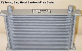
C) Setrab, Mocal, Earl "Sandwich-Plate" Cooler : Ideal.
Whilst costing more, they are the factory grade solution chosen by marque the world over for their reliability, efficiency & compact size both in production & racing-team use. Setrab # 616-6, 16-row, 4.75" x 13", 6AN fitting, cooler, 101$US. Setrab # 619-6, 19-row, 5.75" x 13", 6AN fitting, cooler, 115$US. www.bakerprecision.com/setrab.htm
D) Setrab, Mocal, Earl "Sandwich-Plate" Cooler with Fan & Thermostat : The real solution.
The problem with all coolers is that they requires air to be flowing over the radiator. Crawling along for an hour in summer heat produces least air flow over the radiator when most is needed.
The solution is an oil-cooler with Fan & Thermstat, so making the maintenance of cooled ATX independent of vehicle speed even in stop & go traffic.

Smaller Mocal 115mm x 16-row Sandwich-Plate Cooler - 46.82, Fan housing for 115mm x 16-row - 20.05, Fan 119mm square, 12V - 22.05, Electric fan thermostat - 7.00
The cost-benefit is simple: 95.92 versus 1,800.00. Costing little more than an oil change service, comparable to the many junk automative "improvement" products out there, and also goes a long way to negating the need for 8.8L of costly Synthetic ATX fluid.
A UK Supplier of Oil Coolers is www.thinkauto.co.uk
Oil Cooler Comparative Sizing :
To underline the undersizing of the stock ATX cooler, the Ford 1.8-engine uses a 24" x 4" ATX cooler, whereas the Mazda 2.5-engine ATX cooler is approximately 70% smaller yet must handle a nearly 50% bigger engine with 60% greater torque & thermal dissipation, and an ATX which is known to have overheating problems in itself.

The compact sizing of the sandwich-plate design can be seen. Following this sizing the Mazda unit should be 12" x 10" in sandwich-plate, or an enormous 28" x 12" in the inefficient tube-&-fin design. Fitting a tube-&-fin cooler will reduce the cooling performance of the engine radiator & air-conditioning condenser.
Cooler Installation
Hose clamps : Minaba hose clamps should be used on oil lines, particularly where maintenance for complete oil changes requires their removal & re-use. Minaba clamps use a double-band rolled-edge construction, no sharp band tails; never leak, clamp all around the hose without cutting it; re-usable. Stainless steel version are available.
Cooler mounting bracket : Situate the ATX cooler in front of the coolant radiator to ensure low temperature air in slow moving traffic. Where a cooler is not mounted by pass-through plastic tags, it may be more ideally mounted to an aluminium L-angle from a hardware store or www.aircraftspruce.com. Aircraft Spruce offer 12"-multiple lengths of 2"x2"x1/8" 03-48400 at 2.20$US, 03-48500 1/4" at 3.60$US, T6061T6 aluminium.
Clutch
Pre-Empt
None, simply use non-OEM part.
Problem
New environmentally-friendly asbestos-free clutches are not as long lived as their previous asbestos versions. The choice appears to be chatter/judder as on some BMWs, or slippage as on our cars. The 2.5V6 coverplate clamping force is 1510 Newtons, just 27% uprating over the 2.0. Unlike asbestos clutches, the non-asbestos units can slip for many thousands of miles before failure.
Workaround
Aftermarket unit such as Centerforce Dual Friction Unit is designed for 90% uprated power but similar clutch pedal weight. It works by a dual-friction clutch-plate & centrifual weights which increase clamping force with RPM, preventing slippage problems.
ACT clutches require some clutch master cylinder rod adjustment, and do involve a heavier clutch pedal. Use of racing-puck clutches or clutches lacking take-up springs must be avoided since the shock loadings on bearings & gearbox will result in failure eventually. They are for racing use, and not road use.
Clutch specification is 225mm 8-7/8" single dry plate with 22x15/16 spline.
CV Boots
Pre-Emptive
Check regularly, maintenance item as & when they tear.
Need To Fix
Once a CV boot tears, the grease is lost and dirt & water can penetrate the joint which is quickly destroyed. CV grease is often sprayed around the inside of a wheel or underside of the engine compartment when a CV boot chairs.
Replacement CV Joints are cheapest from aftermarket suppliers: - USA - www.raxles.com do NEW (not remanufactured) outer CV joints, including ABS rings if required, both MTX & ATX joints are available. The use of remanufactured joints is not recommended for outer joints due to the greater angle the joint is subjected to and remanufacturing destroying the case hardening of the joint resulting in a materially weak construction.
CV Boot/Joint Installation
Many thanks to Ethan Vos (Probe Mailing List) for these instructions.
Once the axle is out of the car the boots may be changed in this manner:
- Remove the clamps from both boots. The easiest way to do this is with a cutoff wheel, but be careful not to hit the steel under the boot.
- Cut the boot from end to end. This will enable you to remove the boot and still see how everything fits together. A sharp knife or carpet scissors works well.
- The inner joint is either a ball and cage design (manual transmissions) or a tripod design (automatic transmissions). In either case there will be a c-clip at the outside of the outer (boot) end of the inner housing. Remove it.
- Carefully pull the tripod or cage assembly out of the housing. Don't worry if the balls fall out of the cage. Worry a lot of the rollers fall off the tripod. You may want to wrap masking tape around the outside of the tripod to make sure nothing happens. I'm being overly cautious here. You'd have to screw up real bad to knock a roller off the tripod.
- Remove the c-clip that holds on the tripod or cage assembly.
- Remove the tripod or cage assembly. The cage assembly will pull off easily. Note that it can go on two ways but only one is correct. The tripod may have to be tapped off with a dead blow hammer. Tap gently on the rollers until it comes off. Be careful not to put any flat spots on the rollers or else you will have a vibration problem.
- When the inner tripod or cage assembly is removed you can clean out the outer joint as well as you can. Don't try to take the joint off the shaft or you may break the end of the axle bar.
- Put the supplied grease into the outer joint. Don't spend a whole lot of time on this. The grease will get properly distributed in about 10 rotations of the axle when it's back on the car.
- Install the boot. Once the boot is in place tighten the large clamp. With the small end of the boot in the proper location on the shaft slide a small screwdriver under the boot to let any trapped air escape. Then tighten the small clamp.
- Slide the small clamp for the inner boot onto the axle and then install the boot. Tighten up the small clamp.
The best clamp to use is the one ear Oitiker type. This is the clamp that is in the EMPI boot kits. If you are careful you can use side cutters to crimp it but the best thing is the proper tool. I think Lisle makes the tool as well as Oitiker. A nail puller or anything that can crimp with two parallel surfaces will work. Tighten the clamp until the boot won't turn on the housing. (My aside, Mazda Main Dealers using cable ties should be taken out and made to change both clutch & timing belt on the V6s in one day).
- Re-install the tripod or cage assembly and c-clip.
- Fill the cleaned up inner housing with grease. (You did clean it didn't you?)
- Re-assemble the inner joint assembly by sliding the tripod or cage assembly into the inner housing. Re-install the large c-clip.
- Tighten the large clamp. It is not necessary to "burp" the inner joint, in fact try to get some air trapped. If the clamps are tightened when the axle is completely compressed and the air is let out of the inner joint, a vacuum will be created. This vacuum is strong enough to pull the axle out of the transmission in some cases.
